I couldn't believe it when Bill produced this piece of equipment which he had stored in his
loft for posterity! The transmitter we had worked on together back in 1969. I'd forgotten it
had a light blue front panel; a colour which MUIRHEAD adopted in the late 1960's for their
transistorised range of test equipment. Another 'foreigner' which somehow managed to found its
way into the company's paint shop!
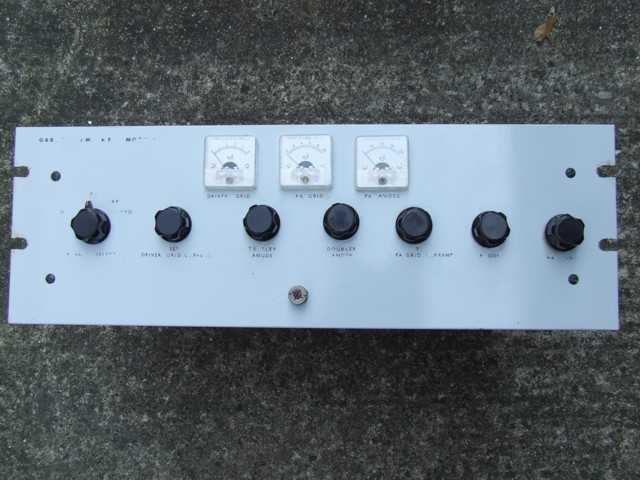
Seeing it again after all these years makes me think perhaps we should have spent a bit more
time measuring up the electronics panels before mounting the components so that the knobs for the
tuning controls lined up centrally! Certainly the QQV06-40A PA anode tuning capacitor knob which is
somewhat offset from the rest. On reflection, I recall this was so, but had no choice but to drill
the front panel to match up with the spindles from the controls on the electronics panels which
were built first.
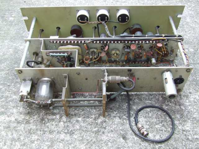
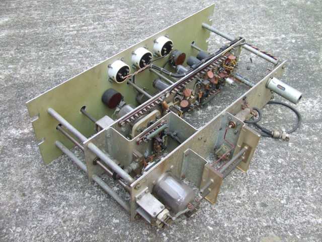
Views showing the internal construction of the 2 metre AM transmitter
The transmitter was originally designed with the QQVO3-20A for the PA which can be seen to the left on
the middle panel, but Bill decided to add the QQVO6-40A with the tuned anode lines and output coupling
loop on the rear panel. The valve to the right acts as a clamp connected to the screen grid of the 640A
and will conduct heavily reducing the PA anode current if the drive excitation fails.
The switch to the right on the middle panel selected a crystal from a bank, but a co-axial socket was
added to allow for VFO control. Stages up from the oscillator acted as frequency doublers/triplers. Using
a 320A to drive a 640A was a bit of an 'overkill', but Bill mentioned there was never a lack of grid drive
to the 640A PA !
Although rated at an input power of 90 Watts, in practice there were problems with flash over across
the vanes of the PA tuning capacitor when modulation was applied. To overcome this, Bill downgraded the
AM modulator and reduced the input power to the transmitter to 20 Watts. I think I would have changed the
tuning capacitor to a higher voltage rating and run the 'full boot' as I've always been a bit of a high
power enthusiast!
It was great to have seen Bill's transmitter again and looking back now it makes me cringe that I have
no equipment that I built (or photos of) from that era. No record of all the hours spent and loving care
I put into building such gear... Such is life!