STUDYING TO BECOME A RADIO AMATEUR
As I never had any training in RF techniques, not even at Bromley College of Technology which I was
attending as a day release electronics student, Bill offered to help me through the course. He advised me
to get a copy of the Radio Amateur's Examination Manual from the Radio Society of Great Britain (RSGB)
and a booklet with past examination papers. Every thursday evening for the best part of 1969, I would go
around to Bill's place with my RAE manual and he would test me on various topics. He would go into great
depth explaining about transmitters and receivers, how to avoid interference and all the other stuff I
would need to know to take the exam. Hopefully, I would be up to speed to sit the winter RAE in London.
I owe a lot to Bill G8BGR, he was an excellent teacher.
Bill was always working on something. His latest project was building a 2 metre
transmitter using a QQV06-40A in the final with tuned copper lines. We worked on this together with me
doing some of the chassis work; drilling and tapping the holes and general metal bashing.
About this time, I decided to make a start and build a 2 metre band converter so that I could at least
receive signals. Bill supplied me with some of the more difficult to obtain components such as the crystal.
The rest of the bits I obtained courtesy of Muirhead! It looked something like as shown in this image and
used three valves, but did not use a miniature NUVISTOR valve for the RF stage that were popular about this
time. I remember very little about building this converter except that the outside of the box and lid I
spray painted an awful pink colour (probably the zinc primer) as I never got around to completing the job.
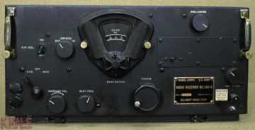
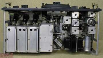
As a tuneable IF (HF receiver), I acquired a BC348R. These were fitted into American and allied bombers
during WWII and were substantially built with a beautifully engineered fine tuning dial. I do recall having
to make a mains power supply for it and with a bit of ingenuity, I managed to fit it into the space where
the rotary voltage converter once sat. This has also been done in the lower image (bottom right). A fine
example of this classic receiver I found at the website of :
KI0LE
Bill used the 10 metre band (28 to 30MHz) at the top end of his AR88LF receiver as a tuneable IF for 2
metres. The BC348R would only tune up to 18MHz, so I had to use a lower frequency. The crystal that I was
given determined this to be 4 to 6MHz. In retrospect, this was a bad choice as I heard more breakthrough from
that band than the 2 metre signals I was searching for. Bill aligned the 2 metre converter for me and I made a
simple dipole antenna. I was now ready to receive signals.
At this time I was still living in SE London and the drive over to Bill's was quite a distance to travel. In
1969, my mother decided to move out of London and during that year she had put a deposit down on a semi-detached
town house still in construction in Biggin Hill, Kent. The house would be available in March 1970. For me this
was excellent news. This new location would give me a great advantage for amateur radio. It was about 600ft
above sea level. Bill explained that with VHF/UHF communications, the higher you are the better. The other
great feature was that I could use the utility room downstairs for a shack.
Receiving tests with Bill on 2 metres were very poor. From the front room of my house in East Dulwich, with
the dipole aerial resting on the windowsill, I could barely hear him. I would have to wait a few more months
until the new house was ready. Biggin Hill to Farnborough is very close and his signals would then be a lot
stronger. In the meantime, I had paid my fee to sit the winter RAE and that time was drawing near.
EXAMINATION DAY
That day in December finally arrived. I made my way up to London to the examination hall where the RSGB
held their bi-annual RAE examinations. I remember this evening well. The president of the RSGB who at that
time was J. W. Swinnerton G2YS (looking very impressive wearing his chain of office) opened the exam and
wished us all good luck then the papers were issued out face down. To me this was no big deal as during this
time I had been taking exams at college and knew the formalities. It was quite amusing glancing around the
exam hall and seeing the faces of the other candidates. Many I could sense were nervous; some were putting
their watches out on the desk or were neatly laying out their pens, pencils and rulers. When the announcement
to start was given, I casually picked up the paper and started to read it through. After about ten minutes,
I thought I'd better make a start as everyone else was busily writing at this time!
From what I recall, there were four compulsory questions in Section 1 on Radio Rules and Regulations. In
Section 2; the technical part, I could select six out of ten to questions to answer. I can't recall what all
the questions were, except one on HF propagation between day and night time hours that I answered. The maths
questions I avoided like the plague. That always was my weakest subject... and still is!
The RAE at that time was a 'written' examination paper. Not like the multiple-choice papers that were
introduced in later years. I recall when working at Bromley College a few years later, a lecturer carried out
an experiment by asking an MV (Motor Vehicle) student if he could fill in question boxes at random on a
multiple-choice examination paper in electronics. He finished it in five minutes flat and achieved 60% ...
A pass! As you will have guessed, I have never had a high opinion of multiple-choice examination papers
where there can only be one correct answer. At least with a written answer examination paper one could get
some marks if the examiner could see if you were on the right track even if the final result was not correct.
I finished the paper well within the three hour time limit and carefully read through what I had done. When
the call was given to stop, I could see many were trying to squeeze in the last few seconds of writing before
their papers were collected. I was fairly confident with my effort, but would have to wait at least a month or
so before I knew for sure. As the weeks passed after taking the exam, I was getting anxious then finally the
long awaited letter from The City & Guilds of London Institute arrived... I had PASSED.
The colourful RAE certificate would arrive in due course, but with the pass notification slip, I could apply
for my Class B license. I wasted no time in mailing my pass slip to the Ministry of Posts and Telecommunications.
On the 19th February 1970, I received my license stating that my allocated callsign would be G8DNC. In
March, my mother and I moved to 55 Hillingdale, Biggin Hill, Kent. I could now start in earnest to set up my
shack.
BUILDING MY 2 METRE BAND AM TRANSMITTER
Still with the house full of packing boxes and tea chests after the move, I set up a provisional bench using
two tea chests and some floor planks. The BC348R and the 2 metre converter sat on this and I rested the dipole
on the window ledge. I certainly had no trouble in receiving Bill. Now living only a few miles away he was very
strong now, but he was the ONLY station I could hear. It was time to start building my transmitter and to put up
a decent antenna if I was to improve things.
Constructing my 2 metre transmitter I remember well. It was a design from the fourth edition of the RSGB
Radio Communication Handbook (pages 7.22/7.23). Some of the components such as coil formers with screening
cans, Bill didn't have in his junk box and suggested that Mike Foster another local amateur, would
probably have them. So, one evening Bill and myself paid Mike G8AMG a visit. His shack from what I can
remember was behind Beckenham cinema on top of an out building with a 14 element 2 metre PARABEAM mounted on
the roof. This was one of the biggest 2 metre antennas available at that time and made by JAYBEAM. I was
impressed the first time I entered Bill's shack, but in comparison, Mike's was like a ham radio junk emporium!
I had never seen so much stuff. Mike had no trouble in finding the components I needed to build my transmitter.
I met Mike quite a few times afterwards. On one occasion I was around at Bill's tuning the band when a ghastly
noise was detected from one end of the 2 metre band to the other. Bill had no explanation for this, presuming it
was a local source of interference. He was certainly right there? Mike came into the shack laughing and showed
us a little circuit he had just built and put into a cigarette packet. A low power, wide band jamming device that
he could plant on unsuspecting radio amateurs if they annoyed him. He mentioned that a certain person was to have
this device thrown over his garden fence shortly! Such was Mike's ingenuity. A really great bloke who later was
heavily involved in setting up the first London 2M repeater GB3LO and in later years the PACKET radio
network.
Now with all the components, work could start on my transmitter. I built this into a die-cast box with the
tank circuit of the power amplifier valve fitted into an aluminium compartment mounted on top. There were two
crystal sockets each capable of holding three HC6U crystals (in the 6MHz range) selectable by a rotary switch.
In practice, I don't think I ever had more than two crystals installed. It was five valve design using two
EF91's and two 5763's driving a QQV03-20A 'output bottle' in the final. I can still recall cutting the large
hole in the box for the valve base. I did this using a fly-cutter in the electricians workshop at Muirhead; a
somewhat precarious and dangerous operation. At this time I was no longer working in the Service Department and
had been relegated back to the main factory.
The power supplies for the transmitter (one for the exciter, the other for the power amplifier) were mounted
on a steel tray with a front panel. On this was eventually mounted the transmit/receive push buttons, a voltmeter
for checking the health of the power supplies and the microphone gain control and input connector. This slid into
the lower half of a 19-inch rack case. Adjacent to the power supply was the AM modulator. This used a pair of
6L6's in the output stage driving a WODEN modulation transformer; an expensive item I had to buy. The blue glow
from the 6L6's was very impressive and flickered when I wound up the mic gain. The design was cribbed from a
Muirhead fax machine motor amplifier circuit. When testing this late into the night, a loud explosion occurred
and something shot past my head at incredible velocity. The shack was filled with smoke and paper foil. I had
made an error and connected one of the electrolytic capacitors in reverse polarity! Another lesson I learned?
Do not built or check over high voltage circuits when almost asleep :-)
G8DNC GOES ON THE AIR
The transmitter needed Bill's expertise to get working. He said they rarely produced enough RF at first. He
tweaked the coils by pulling or squeezing them. After a short time the transmitter was producing the expected RF
output and could easily light a 40W light bulb. Now with a working transmitter I could finish off the metal work.
I fitted the box on to a front panel with the transmitter tuning controls projecting through the front panel on
extended spindles and added meters to measure grid and anode (plate) current. A couple of years later I added an
FM phase modulation module, but this was never very successful.
The 19 inch case with its two racks was very impressive and weighed a ton! Certainly the biggest home project
I had accomplished at that time. With the front panels (sprayed painted silver hammer at Muirhead) and the
control functions labelled using LETRASET, it looked the business. Did it work? Yes, it loaded up beautifully
into my dipole and Bill gave me a 5-9+ report from Farnborough. G8BGR being my first logged contact on
amateur radio.