RADIO AMATEURS GO ON HOLIDAY
In the summer of 1970, Bill asked me if I was interested in going on a camping holiday for a week in
Woolacombe, North Devon. We would be accompanied by two other radio amateurs; Bryan Harber G8DKK
and Martin Emmerson G3OQD. Although I had met Bryan a few times at Bill's place, Martin I knew
only by name and for his reputation as an excellent home constructor. I received a copy of the RSGB Radio
Communication Handbook (Edition 4) for Christmas and in the SSB section, were the constructional details
and circuit diagrams for an HF band solid state transceiver (with a valve PA stage) which Martin had
designed and built in the 1960's. A time when such pieces of gear were not easily obtainable. I still
keep in contact with Martin to the present day.

Bill and myself met up with Martin at his parent's bungalow tucked away in the trees below Hayes Common
shortly before we went on holiday. Martin's shack was impressive. Not only his home built HF gear, but with
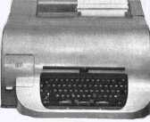
a Creed 54 teleprinter and a RTTY terminal unit which he had built taking up much of his bench space. Seeing
this inspired me in later years to get on to the data modes available to the radio amateur. His HF rig looked
impressive in the photos in the RSGB Handbook, but to see for real the detail
Martin went to produce such a professional looking piece of gear was incredible. The case construction, the
lettering and numbering of the front panel and frequency dial was a 'work of art' and is something that I have
attempted to emulate in my home built projects every since.
I recall the drive down to Devon well. Bill was with me and Martin and Bryan leading the way. Martin had
this tall, strange looking mobile antenna fitted to the rear bumper of his car. Martin later told me the
curious contraption on top of the aerial was called a 'capacity hat' enabling it to load up on all the HF
bands. The holiday itself was uneventful. It rained most of the time. In the evenings, Martin would sit in
his car perched on the cliff top and 'work the world'. I remember one of his contacts was a 'PY'. Being
just a 2m VHF'er, I had no idea where that was and was well impressed when he said his contact was in
Brazil.
TIME I GOT A BETTER ANTENNA !
During 1970, I had many contacts with Bill and a few other local stations, but realised that to get
anywhere further, I needed a decent beam antenna. I recall going to an RSGB amateur radio exhibition that
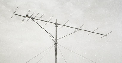
year and purchasing a 10 element 'Long Yagi' from JAYBEAM (photo courtesy of Paul Lyon G8BIS).

To get past the gable of the house and to raise the antenna to a respectable height, I would need two 12ft
lengths of 2 inch aluminium tubing. These along with a tube coupling and wall brackets I ordered separately
from Jaybeam. To mount this antenna was fun; probably dangerous would be more correct! I hired an extension
ladder and mounted the wall brackets adjacent to the upstairs landing window. I couldn't afford the luxury of
a rotator and knew I would have to rely on the ARMSTRONG method of rotation. Once the brackets were secured,
I assembled the antenna onto a 12ft tube and slowly pushed it up through the U-bolts. Once the bottom of the
tube was almost at the lower U-bolt, I bolted on the coupling, fed in the second 12ft tube, carefully removing
the U-bolts one at a time then continued pushing up and twisting the mast until it was in place. I mounted a
plate at the bottom to prevent the mast from slipping down then clamped up the U-bolts just enough so that I
could reach out of the window and turn the mast by hand. In practice, this method was never very successful
and eventually I kept a pipe wrench handy on the windowsill! I ran the feeder cable (UR67) down the side wall,
across the front door and into the shack by drilling a half inch diameter hole through the window frame. In
later years there was a row of these holes. It would be interesting to pass by the house one day to see if they
are still there.
The antenna was very impressive; too impressive in fact! It dwarfed the TV aerials and more to the point,
swung over the neighbour's house when pointing east. This was shortly to give me plenty of grief. I was soon
putting out a good 2 metre signal from Biggin Hill. One of my best DX contacts at that time being with a
station up in Horncastle, Lincs. In the summer of 1970, I built my first item of transistorised equipment for
amateur radio; another 2 metre converter. This was to be my last Muirhead 'foreigner' as within a couple of
months I was to leave the company.
TROUBLE AT MILL (MUIRHEAD)
I had completed my 5 year apprenticeship, received my indentures and had worked another year basically
to keep up my college studies. In my third year of studying for the City & Guilds Electronics Servicing
Certificate, Muirhead decided to stop my day release using the excuse that I was 'too old'. I was 22 at the
time! This was a bare faced lie as some other ex-apprentices and trainees older than me were permitted to
continue with their studies.
This was certainly instigated by 'Major' Wray. A pompous, self opinionated ex-army type who was the training
officer at that time. He was a nasty shit and we never got on well! Probably my long hair, jeans and T-shirt
attire wasn't to his liking. Not forgetting to mention that in 1966, I got expelled from my previous day
release college (SELTEC) in Lewisham, SE London, by Adams (the principle) for calling him, "A Sarcastic
Bastard" to his face... Of which he WAS :-)
I recall the occasion when Wray hauled me into his office saying, "Mills, your future with this company
is rather nebulous." To which I replied he could 'shove the job where the sun don't shine' as I had found
employment elsewhere... A most enjoyable experience!
It was ironic that I should be offered a better paid job in the very same college that I had been attending
as a day release student since 1967. My course lecturer said it was a waste of time me continuing working at
Muirhead as he had tried also to convince them to let me continue with my studies, but they wouldn't permit it.
At least working at the college I could continue with my electronics course which I finished gaining credits
and distinctions in 1972.
I START A NEW JOB
In September 1970, I left Muirhead and started working as an electronics technician at BROMLEY COLLEGE
OF TECHNOLOGY (now called Bromley College of Further and Higher Education). I thought Muirhead was a good
place to work regarding facilities for building 'homers, but the college was something else! Here I had my own
workshop albeit in the beginning just a caged storeroom between the electronics labs. I had my own bench, test
equipment and elsewhere on the campus, facilities for metal working. Later, I set up an area for printed circuit
board manufacture. The chief and senior technicians; George Redway and Peter Robinson, were very reasonable
bosses and I generally got on well with them. My first job I recall was to sort out the store, clear out the
junk, tidy up and restock the component trays. Other than the times I was expected to set out and clear up the
labs, prepare experiments for the students or repair faulty lab gear like oscilloscopes and signal generators,
my time to some extent was my own.
I BUILD A DEDICATED 2 METRE RECEIVER
Back in my shack, the BC348R although now running with a more sensitive transistor 2 metre converter was
still the weak link in my station. The breakthrough I got using a tuneable IF of 4 to 6MHz was terrible. It
was time to build a receiver specifically for the 2 metre band. Perhaps later, adding a 70cms converter. So
I decided to approach this from first principles. This would be a tuneable IF covering the band 26 to 28MHz
using double conversion to 1.6MHz and then down to 470KHz and would be built in a modular form using printed
circuit boards with each sitting in its own screened compartment. This receiver was also part of my course
work as day release students were expected to do a certain amount of practical work as well as theoretical
studies.
I started from the back end of the receiver by first building a small audio amplifier. Once this was
tested and working, I started work on the 470KHz IF strip (using BF115's) and the detector stage. I stripped
down old radios in the store for suitable IF transformers. These radios were issued out to students to repair.
I would put on different faults and it was up to the students to find them... Great fun! Eventually some of
these radios would become unserviceable due to the PC board tracks falling off.
I built the 470KHz IF strip on matrix board and later added an AGC amp with an RF gain control and S-meter
circuit. I then worked on the 1.6MHz first IF stage comprising of a crystal oscillator with an FET mixer. Once
these units were working correctly, I made PC boards for them and re-mounted the components. It was rewarding
to see the modulated carrier peak up on the oscilloscope. To move the probe along to the detector stage and
see the demodulated 400Hz audio signal and to hear the tone coming through the loudspeaker. At last with the
help of my course lecturer Ernie Bransden (see footnote), I was putting theory into practice.
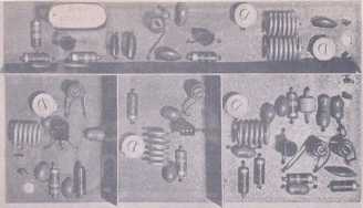
In the meantime, Bill had built yet another 2 metre converter. This time a kit from a German company and
designed by DL6SW (see image). This used FET's (3819's) in the RF stages and according to Bill was excellent.
I too followed suit and built one of these kits to mount in the receiver. This would be the last 2 metre
converter I would build.
The tuneable 26 to 28MHz front end of the receiver was the most difficult part to get working. I spent
weeks on this. It was built into a small die-cast box and had a Jackson 3 gang variable capacitor mounted
on top. Inside the box was a plain copper board with two dividing partitions; the RF and mixer stages
(using 2N3819 FET's) and the local oscillator being mounted in these compartments using stand-off pillars
and feed-through links. To get all three sections tracking together was a nightmare. I padded here, trimmed
there and with Ernie's help eventually managed to get the wretched thing to work. I also built a BFO board
so that I could resolve SSB transmissions that had just started to make an appearance on the 2 metre band.
The aluminium chassis was made as a tray with the front bent up to form a front panel. I divided the tray
into compartments for each PC board. There was plenty of space to add a 70cms converter in the future,
but I never did. I mounted a Jackson slow motion drive to the tuning capacitor and on this was fitted a dial
using a Perspex disk. I cut an aperture in the front panel, but the dial never got calibrated either. In
practice, the receiver worked quite well and was a lot more sensitive than my BC348R. Although the breakthrough
problem disappeared, I discovered an annoying 'birdie' in the tuneable range. After doing the sums, I realised
this was due to using a tuneable IF of 26 to 28MHz. I changed the crystal in the converter (must have been to
38.6666MHz) and tweaked the local oscillator frequency to give me a tuneable range of 28 to 30MHz... Lo and
behold, the birdie (tweet, tweet!) disappeared :-)
This receiver along with my monstrous AM transmitter rack and 10 element long yagi were to serve me well for
the next couple of years. This home constructed equipment has long since gone as well as the BC348R and my
early 2M converters. I recall donating my AM transmitter to the college when I moved over to 2 metre band FM
operation in the mid 70's, but the whereabouts of the receiver is a complete mystery. I still have the circuit
diagrams I made for it (circa 1972) to reminisce over. A pity...
Footnote
Ernie Bransden was my course lecturer at BCT from 1967 until when he left the college to start his own
business around 1972. He had designed and patented a novel contact-less electronic ignition system and
recall him demonstrating the prototype to my class. He later went on to form the company
BOYER BRANSDEN IGNITIONS which I am pleased to see are
still going strong after more than 30 years and selling their systems world wide. A brilliant electronics
engineer (and ex-college lecturer) who taught me much of what I know... Thanks Ernie!


